Universal remote control for Arduino. Transmitting data in the infrared range using Arduino Connecting an infrared receiver to arduino
There are many articles on the Internet about how to make your own TV remote control using Arduino, but I needed a universal remote control to control my TV and media player. The main advantage of my universal remote control is that the buttons in the Android phone application are dual-purpose, but look at the video.
The remote control is very convenient in that almost the same buttons on the screen are used to control the TV and player. One difference is that the " AV"in TV control mode changes to a button" ◻
" (stop) when switching to the player control mode. The pictures show two modes, on the left is the TV control mode, on the right is the player control mode.

Well, now I’ll tell you a little about creating such a remote control. For the device I used the remote control for the ERGO TV and the remote control for the DUNE HD TV101W media player.

To receive data from the remote controls, I used an infrared sensor TSOP1138 (analogous to TSOP4838) at an operating frequency of 38 kHz and connected it to the Arduino board according to the scheme:


This sketch will not be needed to determine the encoding of data transmission and read the code of the remote control buttons.
In the sketch in the line int RECV_PIN = 11; indicate our pin number 4
After uploading the sketch, open the “port monitor” and, pressing the remote control buttons, look at the received data.

The picture shows an example of scanning the power button from the TV remote control and the player remote control. Now we create a table for button codes.

I got it like in the photo above. Under the inscription TV TV remote control button codes; under the inscription Player- codes from the media player remote control.
Now we disconnect our infrared signal receiver from the Arduino board and connect the HC-05 Bluetooth module and an infrared LED to it according to the diagram in the photo.

After that, we move directly to the sketch.
Sketch
#include
In the sketch you will need to edit the button codes, namely in the lines:
If (x == 97) ( irsend.sendNEC(0x807F08F7, 32); delay(40);
Change the value 807F08F7 to:
If (y == 1) ( //button codes for the TV remote control if (x == 97) ( irsend.sendNEC(0x12345678, 32); delay(40); )
Where 12345678 is the code for your button.
After editing the sketch using your button codes, upload the sketch to the Arduino board and proceed to installing the application on your phone.
We turn on Bluetooth in the phone, look for our device, create a pair, then launch the application Pult on the phone.
Upon startup we will have a screen with a red bluetooth icon in the lower right corner, which signals that we are not connected to our device.

After that, click on this icon. We should see a window with a list of all available bluetooth devices, where we select our device to connect.

Now we are back on the main screen and can already control the TV:
To switch to control mode we need to press the button labeled "Player". As I said earlier, our button labeled "AV" will change to a button " ◻ ":
To disconnect from our device, simply hold down the “Power” button for a few seconds.
Well, a few photos of my finished device.


It turned out quite well, it seems. I'm waiting for comments on the article.
It sends a packet of encoded and modulated data to the IR LED, and when the button is held down, also repeat packets.
The device can be useful if you assign unused buttons on the television remote control (for example, the colored teletext buttons) to control the lighting in the room.
Instead of incandescent lamps, you can connect any ~220 V network device with a current consumption of up to 2 A.
We will need:
- IR remote control x 1pcs (any TV IR remote control will do)
- Devices (lamps) that we will control x 3 pcs.
To implement the project we need to install the library:
- Library iarduino_IR for working with IR transceivers
IMPORTANT: the library uses a second hardware timer,
DO NOT OUTPUT PWM SIGNALS TO 3 OR 11 OUTPUT!
You can find out how to install libraries on the Wiki page - Installing libraries in the Arduino IDE.
Video:
Connection diagram:
This circuit uses only digital modules; they can be connected to any (both digital and analog) Arduino pins. For example, we connected all modules to analog outputs. Not everyone knows that Arduino analog pins can work as regular digital pins, allowing you to receive (from an IR receiver) and transmit (to solid-state relays) digital signals in the form of logical “0” and “1”.
If you will connect devices to other pins, then their numbers must be indicated in the second (IR object declaration) and third (pinRelay array declaration) lines of the sketch. The program code is written so that you can connect as many relays as there are free pins on your Arduino, simply by listing the pin numbers in the third line of the sketch (pinRelay array declaration).

Work algorithm:
- At start, the sketch assigns the IR remote button code to each solid state relay sequentially. First, the LED blinks and the circuit of the solid-state relay is closed, the output of which is indicated first. If you press any button on the IR remote control, the code for that button will be assigned to that relay and the next one will start blinking, and so on, until all relays have been assigned buttons on the IR remote control.
- After appointmentButton functions, all relays are off. If you press the IR remote control button, the relay to which the code of this button is assigned will turn on. If you press the indicated button again, the relay will turn off. The device will not respond to pressing buttons whose code has not been assigned to any relay.
- If If you don’t want to assign button codes at every start, then explicitly indicate them when declaring the varRelay array, and remove the for and while loops from the setup code.
- Find out the code for each button you can write the following line: if(IR.check())(Serial.println(IR.data);)
Program code:
#includeIt is nothing more than a VS1838B IR receiver with the manufacturer’s recommended harness installed on the board.
To work with this module out of the box, you need a remote control with a frequency of 38 kHz.
The advantage of this board is the push-in connector, which allows you to replace the IR receiver with another one operating at the frequency required for your project without soldering.
Main technical characteristics:
Supply voltage: 2.7 - 5.5V
Modulation frequency: 38kHz
Temperature range: - 20 ... + 80°C
Interface: Digital
Connecting to Arduino
The module is equipped with a three-pin 2.54mm connector
: connects to GND pin
: connects to +5V output
: connects to digital pin (D2 in example)

An example of working in the Arduino environment
To work with this module you need to install the IRRemote library
Download, unpack and put it in the libraries folder in the Arduino folder. If the Arduino IDE was open at the time of adding the library, reboot the environment.
Reading remote control buttons
To read the remote control readings, fill in the sketch below. It will output the encoding of the pressed buttons to the port.
As an example, we will use the remote control, as in the picture, because This type of remote control is included in the set
You can read about the differences in the operating logic of various remote controls in the original article from a member of our community under the nickname

Sample code:
#includeYou should see the following in the port monitor:
By holding each button for almost a second, we get about 10 codes. The first one is the button code. And after it, a standard code begins to appear, which reports that the button is stuck.
Controlling Arduino board with remote control
Let's make the LED on the Arduino board (D13) light up when the first button is encoded and turn off when the second button is encoded.
Sample code:
// Tested on Arduino IDE 1.0.3#includeGood day everyone (or night, as you wish), let’s start with a lyrical introduction. Nowadays many people have houses TV with remote control, tuner, DVD player . Many people (and families) cannot imagine their home life without a remote control in their hand. Agree - how great it is to be the master of home appliances, and at any moment dictate your will to these pieces of hardware. In this article, we would like to look at remote control technology in more depth, and give some examples of application for our needs.
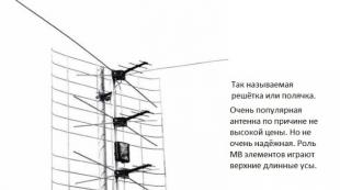
So, what do we need as components for our experiment? As an option ready-made IR remote control and IR receiver modules are sold. But we don’t want to wait and pay money, so we will act more hardcore. Let's take as a basis a remote control of unknown origin, we also have a piece of a board from a Chinese tuner on which an infrared receiver is soldered. In the photo below you can see these components. To be honest, the remote control was found among unnecessary junk in the office desk, and the board with the IR receiver was taken from the nearest radio repair shop.

Well then, as I used to say Hannibal - "Forward to Carthage" . We just need to unsolder the receiver and connect it to the board Arduino according to the following scheme...
- Connecting an IR receiver
IR receiver which was soldered from the board does not have any markings, it is just another unknown Chinese radio component, of which thousands were produced. In short, we can say - in one building it combinesphotodiode, preamplifier and driver . The output is formed by a normalTTL signal without padding, suitable for further processing by the microcontroller. The carrier frequency is possibly (!) 36 kHz, but now this is not so important... Let's just try to connect it to the boardArduino , the conditional diagram will give the desired pinout of this device. In the diagram below, highlighted in red is the shape of the body in which ours is madeIR receiver , highlighted in green - pinout by which it is connected to the boardArduino .

Attention!!! On the Internet there are many pinout diagrams for devices in such a package (TSOP). The pinouts given in this article may not coincide with any found on the Internet, but this is how everything is connected to us. If the IR receiver starts to heat up when connected, immediately turn off the assembled circuit; this means that the connection pinout does not correspond to the actual one, and you will have to select it almost at random. This is exactly what we did, because the circuits found on the Internet were not suitable for our IR receiver. Here, in general, the main thing is not to burn the Arduino board, proceed with caution!!!
- IRremote library
So everything is connected. There is a library to read codes from the remote control IRremote.h, it is with its help that we will study our remote control, or rather the button codes. In the future, we will use the read codes for our own purposes. The sketch with which button codes will be read is presented in the examples of this library, it is called IRrecvDemo. Attention!!! When compiling the sketch, it gives an error; at the very beginning, you need to add two more plug-in libraries:
#include "boarddefs.h" //Additional library #include "IRremote.h" #include "IRremoteInt.h" //Additional library int RECV_PIN = 2; //Pin for connecting the output signal from the IR receiver //Create an instance of the IRrecv class, passing the pin for connecting the signal from the IR receiver as a parameter IRrecv irrecv(RECV_PIN); decode_results results; //Variable for saving the received code of the pressed button void setup() ( Serial.begin(9600); irrecv.enableIRIn(); //Enabling the IR receiver to work ) void loop() ( if (irrecv.decode(&results)) //If an event occurred/the button was pressed ( Serial.println(results.value, HEX); //Output the code of the pressed button in hexadecimal form to the port monitor irrecv.resume(); //Read the next value/button ) delay(100 ); )
After the sketch has been uploaded to the boardArduino(we use Arduino Nano on the shield I/O Wireless Shield for Nano ), can be opened port monitor and see what codes appear when you press the buttons on the remote control. The result of the sketch is shown in the screenshot below:

By the way, as port monitor We use our proven software, if anyone is interested, you can read the article and download Serial Monitor Pro.
#define KEY_ONOFF 0x807F807F //On/Off button #define KEY_MUTE 0x807F48B7 //Mute button #define KEY_1 0x807F00FF //Button 1 #define KEY_2 0x807FE01F //Button 2 #define KEY_3 0x807F609F //Button 3 #define KEY_4 0x807F20DF //Button 4 #define KEY_5 0x807FD02F //Button 5 #define KEY_6 0x807F50AF //Button 6 #define KEY_7 0x807F10EF //Button 7 #define KEY_8 0x807FF00F //Button 8 #define KEY_9 0x807F708F //Button 9 # define KEY_0 0x807FC837 //Button 0
And now, in general, everything is ready for the final test - this will be an elementary test of controlling the on/off of relay modules. Here's a small task:
- We use two relay modules
- We bind relay No. 1 to button “1” of the remote control
- Relay No. 2 is tied to button “2” of the remote control
- Turning on any of the relay modules is done by pressing the button to which it is assigned
- Turning off any of the relay modules is also done by pressing the button to which it is assigned
- Pressing the On/Off button unconditionally turns off both relay modules (if they were turned on, or one of them is turned on)
A sketch that implements the above task:
#include "boarddefs.h" //Additional library #include "IRremote.h" #include "IRremoteInt.h" //Additional library #define KEY_ONOFF 0x807F807F //On/Off button #define KEY_1 0x807F00FF //Button 1 #define KEY_2 0x807FE01F //Button 2 #define RELOUT1 3 //Output port for relay 1 #define RELOUT2 4 //Output port for relay 2 int RECV_PIN = 2; IRrecv irrecv(RECV_PIN); decode_results results; static boolean REL1_ONOFF = false; static boolean REL2_ONOFF = false; void setup() ( pinMode(RELOUT1, OUTPUT); pinMode(RELOUT2, OUTPUT); Serial.begin(9600); irrecv.enableIRIn(); // Start the receiver ) void loop() ( if (irrecv.decode(&results )) ( switch(results.value) ( case(KEY_ONOFF): REL1_ONOFF = false; REL2_ONOFF = false; break; case(KEY_1): if(REL1_ONOFF) REL1_ONOFF = false; else REL1_ONOFF = true; break; case(KEY_2): if(REL2_ONOFF) REL2_ONOFF = false; else REL2_ONOFF = true; break; ) irrecv.resume(); ) digitalWrite(RELOUT1, REL1_ONOFF); digitalWrite(RELOUT2, REL2_ONOFF); delay(100); )
And at the end of the article there is a video that demonstrates the work of both sketches. If you wish and have creative imagination, you can expand the fleet of plug-ins and manage everything in a more advanced way. In our article, we tried to give a basic example of the application of this technology. Thank you for your attention and enjoy watching!!!
Please enable javascript for comments to work.
There are many articles on the Internet about how to make your own TV remote control using Arduino, but I needed a universal remote control to control my TV and media player. The main advantage of my universal remote control is that the buttons in the Android phone application are dual-purpose, but look at the video.
The remote control is very convenient in that almost the same buttons on the screen are used to control the TV and player. One difference is that the " AV"in TV control mode changes to a button" ◻
" (stop) when switching to the player control mode. The pictures show two modes, on the left is the TV control mode, on the right is the player control mode.
Well, now I’ll tell you a little about creating such a remote control. For the device I used the remote control for the ERGO TV and the remote control for the DUNE HD TV101W media player.
To receive data from the remote controls, I used an infrared sensor TSOP1138 (analogous to TSOP4838) at an operating frequency of 38 kHz and connected it to the Arduino board according to the scheme:
This sketch will not be needed to determine the encoding of data transmission and read the code of the remote control buttons.
In the sketch in the line int RECV_PIN = 11; indicate our pin number 4
After uploading the sketch, open the “port monitor” and, pressing the remote control buttons, look at the received data.
The picture shows an example of scanning the power button from the TV remote control and the player remote control. Now we create a table for button codes.
I got it like in the photo above. Under the inscription TV TV remote control button codes; under the inscription Player- codes from the media player remote control.
Now we disconnect our infrared signal receiver from the Arduino board and connect the HC-05 Bluetooth module and an infrared LED to it according to the diagram in the photo.
After that, we move directly to the sketch.
Sketch
#include
In the sketch you will need to edit the button codes, namely in the lines:
If (x == 97) ( irsend.sendNEC(0x807F08F7, 32); delay(40);
Change the value 807F08F7 to:
If (y == 1) ( //button codes for the TV remote control if (x == 97) ( irsend.sendNEC(0x12345678, 32); delay(40); )
Where 12345678 is the code for your button.
After editing the sketch using your button codes, upload the sketch to the Arduino board and proceed to installing the application on your phone.
We turn on Bluetooth in the phone, look for our device, create a pair, then launch the application Pult on the phone.
Upon startup we will have a screen with a red bluetooth icon in the lower right corner, which signals that we are not connected to our device.
After that, click on this icon. We should see a window with a list of all available bluetooth devices, where we select our device to connect.
Now we are back on the main screen and can already control the TV:
To switch to control mode we need to press the button labeled "Player". As I said earlier, our button labeled "AV" will change to a button " ◻ ":
To disconnect from our device, simply hold down the “Power” button for a few seconds.
Well, a few photos of my finished device.
It turned out quite well, it seems. I'm waiting for comments on the article.